Resistors are considered to be the most used and the most important
component of all the electronic circuits. Take a look at the working,
types and also use of resistors in the field of electronics.


We know that the basic idea of any
electronic circuit is the flow of electricity. This also is further
categorized into two – conductors and insulators. Conductors allow the
flow of electrons, while insulators do not. But the amount of
electricity that we want to pass through them depends on the resistors.
If a high voltage is passed through a conductor such as a metal, the
whole voltage passes through it. If resistors are introduced, the amount
of voltage and current can be controlled.
Thus “resistance can be defined as the ease with which something will let electricity flow through it”.
A conductor has lower resistance than an
insulator. The amount used by the resistor to control the electrical
circuit is termed as the resistance.
What is Resistance?
The definition of resistance is based upon the Ohm’s law given by the German physicist Georg Simon Ohm.
The Ohm’s Law states that the voltage
[V] across a resistor is directly proportional to the current [I]
flowing through it. Here, its resistance [R] is the constant of
proportionality.
Therefore, V = I * R
Unit of resistance
The SI-unit of resistance is Ohm [Ω].
The higher multiple and sub-multiple values of ohm is kilo ohms [KΩ],
mega ohms [MΩ], milli ohm and so on.
Thus, the resistance can be
defined as the voltage required for making a current of 1 ampere to flow
through the circuit. If the circuit requires 100 Volts to make 1 ampere
flow, then the resistance is 100 Ohms.
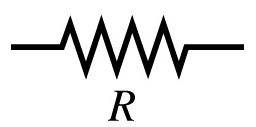
Symbol of Resistor
Resistor is a 2 terminal passive device. The symbol is given below.
Working of Resistor
The working of a resistor can be
explained with the similarity of water flowing through a pipe. Consider a
pipe through which water is allowed to flow. If the diameter of the
pipe is reduced, the water flow will be reduced. If the force of the
water is increased by increasing the pressure, then the energy will be
dissipated as heat. There will also be an enormous difference in
pressure in the head and tail ends of the pipe. In this example, the
force applied to the water is similar to the current flowing through the
resistance. The pressure applied can be resembled to the voltage.
Resistor Series and Parallel Circuits
There may be cases where two or more
resistors should be connected in a circuit. The simplest way of
connecting them is in the series and parallel ways.
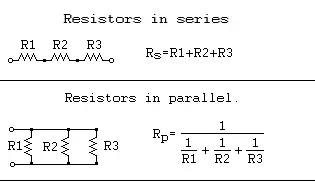
In a series connection, the resistors
will be connected in a series path and the current flowing through the
resistors will be the same. The voltage across the resistors will be
equal to the sum of voltages across each resistor. Here is a figure of
resistors connected in series. Three resistors R1, R2, and R3 are connected in series. The total resistance Rtotal is given by
Rtotal = R1 + R2 + R3

In a parallel connection, the resistors
will be in a parallel path and the voltage applied across each component
will be the same. The current across the resistors will be equal to the
sum of currents across each resistor. The above figure shows a parallel
connection of resistors. Three resistors R1, R2, and R3 are connected in parallel. The total resistance Rtotal is given by
1/Rtotal = 1/ R1 + 1/ R2 + 1/ R3.
Therefore, Rtotal = R1 * R2 * R3 / R1 + R2 + R3
Power Dissipated in a Resistor
The power dissipation of a resistor is given by the equation
Power, P = I2 * R = V * I = V2 /R
The first equation was obtained from Joule’s first law, while the other two were derived from Ohm’s law.
Types of resistors
The most commonly used resistors all
look the same. They look like a small worm with coloured stripes on the
side. There are many types of resistors available. The most common one
ceramic rod wound by copper wires on the inside. The number of copper
turns and the thickness of the copper determine the resistance of the
component. The more the turns and lesser the thickness, the more the
resistance. There are also resistors with spiral patterns of carbon,
instead of the copper winding. Such resistors are used for making
smaller value resistors. Let us take a closer look at all the resistors.
1. Wire-wound Resistors
The resistors with a ceramic rod wound
up with copper wires are called wire-wound resistors. Such resistors
have the effect of inductance as they have copper windings. Even though
the wires are wound in sections with alternate reversed condition an
inductance is produced. Thus, different types of windings are used. One
type of winding is called the flat thin former method which helps in
reducing the cross-sectional area of the coil to a great extent. There
are also other types of windings called Ayrton-Perry winding and bifilar
winding. Some wire-wound resistors have an aluminium case so that they
can be connected to heat sinks which dissipate heat.
2. Carbon Composition Resistors
They are usual resistors with a
resistive element in the shape of a cylinder. The resistive element is a
mixture of carbon powder and ceramic. This mixture is held together
with the help of a resin. This mixture is embedded with wire leads. This
is then attached to wires made of lead. The value of the resistor can
be found out by a method called colour coding, which is painted onto the
outer body of the resistor.
If the concentration of carbon
increases, the resistance of the component decreases. This type of
resistor is not used so commonly now. Though this resistor was highly
reliable, their overheating and overvoltage characteristics are not so
reliable.
3. Carbon film
This type of resistor is applicable for
circuits working under a range of temperatures. The resistor is made by
depositing a carbon film onto an insulating substrate. They can operate
at a range from -55 °C to 155 °C. The voltage range varies from 100
Volts to 650 Volts with a resistance from 1Ω to 10 MΩ.
4. Thin and Thick Film Resistors
This type of resistor was the backbone
of the popular surface mount device resistors used now. The names
differentiate in the manner in which the film is applied onto the
cylinder.
For a thin film resistor, vacuum
deposition method is used to include the resistive material onto the
insulating substrate. This type of resistor is commonly used for making
printed circuit boards. This type of resistor produces accurate
resistance as the whole process of its making can be controlled.
Thick films are also produced in the
same manner as a thin film. But they also have some additional compounds
like glass and also a screen printing liquid.
Both of them vary in their temperature ranges as well as prices. Thin films are more expensive than thick films.
5. Metal Film Resistors
This type of resistor is made by coating
with nickel chromium [NiCr]. The process of making this resistor is
similar to that of thin film resistors. The difference will be in the
compounds used.
6. Ammeter Shunt Resistor
This is the most unique type of resistor
which is used for current sensing. It has four terminals and is used in
the milliohms and microohms range. Though they are used for measuring
small currents, if the current is allowed to pass through a shunt
mechanism, they can be used for measuring high currents as well. Through
this mechanism the current is measured with accordance to the voltage
drop across it.
The shunt mechanism consists of two
brass blocks. Inbetween them are strips of low temperature co-efficient
of resistance alloys. Large bolts threaded into the blocks make the
current connections.
There are also other types of resistors
like lead arrangement resistors, grid resistors and so on. There are
also variable resistors like the tapped resistors, metal oxide varistor
(MOV) and strain gauge.
Colour Coding
The value of the resistance is found out
by colour coding. The resistors have a band of colours shown in their
outer covering. Here are the steps to determine the value of the
resistor.
- All resistors have three bands of colours, followed by a space and then a fourth band of colour. The fourth band of colour will be brown, red, gold or silver.
- To read the colours turn it to the position such as the three consecutive colours come on the left and then the space and the rest of the colours.
- The first two colours from the left indicate the first two digits of the value. The third colour represents the digital multiplier. That is, it indicates how much you have to multiply the first two numbers with. Thus if you have a resistance with the first three colours being brown, black and red, the value of resistance is 10*100 = 1000 ohms or 1K.
- The last band, after the space indicates the tolerance of the resistor. This indicates the range of accuracy of the resistor. Thus, along with the three colours above, if the fourth colour is gold, it means you have a tolerance between +/-5%. Thus the actual value of the resistance can be between 950 Ohms and 1K.
- There can also be resistors with five colours. If so, the first three represents the digits, the fourth will be the multiplier and the fifth will be the percentage of tolerance. This indicates that a more precise value of the resistor used can be obtained from a 5-colour resistor.
Take a look at the colours and their associated numbers given below.
Uses of Resistors
Though resistors can cause wastage of electricity, it has a lot of advantages and applications in our daily life.
- Resistance is one of the main ingredient in the working of a light bulb. When electricity passes through the filament of the bulb, it burns bright as it turns extremely hot due to its smaller size. Though this mechanism wastes a lot of electricity, we are forced to use it to obtain light. The light used nowadays are highy efficient than the older incandascent lamps.
- The similar filament working is the main ingredient in the working of some of our usual household stuffs like electric kettles, electric radiators, electric showers, coffee makers, toasters, and so on.
- The application of variable resistance is also helpful to us. Our TV’s, radios, loud speakers and so on work on this principle.


No comments:
Post a Comment