
MP3302
MP3302 is a boost converter IC
specifically designed for LED drive applications. The MP3302 can drive
27 LEDs (9 strings of 3 white LEDs in series) from a Lithium ion
battery. The IC has internal power MOSFETs for driving the LEDs and has
an efficiency of 88%. Switching frequency is 1.3MHz and the internal
current limit is 1.33A. Other features of the MP3302 are open load shut
down, thermal shut down, under voltage lock out etc. Applications of
Mp3302 are LED back lights, LED based lighting gadgets etc. Functional
block diagram of the MP3302 is shown below (Fig1).

The IC uses a constant current , peak current mode step up regulator
scheme for regulating the current through the LEDs. At the beginning of
each oscillator cycle, the control circuitry switches the power MOSFET
ON. For preventing sub harmonic oscillation, a stabilizing ramp signal
is added to the current sense amplifiers output and the resultant signal
is given to the non inverting input of the PWM comparator. When this
resultant voltage is equal to the voltage at the PWM comparator’s
inverting input (output voltage of the error amplifier), the power
MOSFET is switched OFF. The error amplifier’s output is the difference
between the feedback voltage and the reference voltage. When the output
voltage drops, the feedback voltage also drops and this in increases
the output of the error amplifier. This in turn increases duty cycle of
the power MOSFET drive signal produced by the control circuitry which
increase the duty cycle of the power MOSFET, it conducts more current
and the output voltage is regulated. Circuit diagram of a 27 LED driver
circuit using MP3302 is shown below (Fig 2).
MP3302 LED driver circuit diagram.

C1 is the input bypass capacitor and C2
is the output bypass capacitor. Resistor R1 is the feedback resistor and
it controls the LED current. The governing equation is: LED current = 195mV /R1.
Resistors tagged R are the current limiting resistors for the
corresponding strings and they can be used for limiting the maximum
brightness of the LEDs. A voltage level less than 0.4V to the EN pin
will shut down the IC and a voltage level greater than 0.7V will enable
the IC. Dimming of the LEDs can be achieved by providing a PWM signal in
the range of 200Hz to 1KHz to the EN pin. The absolute minimum
amplitude of the PWM signal is 1.5V. The built in open load protection
circuit will shut down the IC when ever the output voltage goes above
38V. The IC will remain in the shut down mode until the power supply is
re switched.
Selection of R1 is shown in the table below.
| LED current (mA) | R1 (ohm) |
| 1 | 195 |
| 5 | 39 |
| 10 | 19.5 |
| 20 | 9.75 |
| 60 | 3.25 |
| 180 | 1.08 |
Notes.
- While designing the PCB make tracks of the current loops, Schottky diode and the output filter capacitor as short as possible.
- C1 and C2 should be ceramic capacitors. C1 must be rated at least 10V and C2 must be rated at least 50V.
- Inductor L1 must be a low DC resistance type.
LED driver circuit with wide input voltage range.
The figure shown below (Fig 3) is of an
LED driver circuit that can be operated from a wide supply voltage
range (3.3V to 18V). This circuit too is based on the MP3302 LED driver
IC. An extra bias circuit comprising of resistor R and Zener diode D is
added inorder to make the ON resistance of the power MOSFET low and
make the chip compatible to high input voltages. This circuit can drive 3
parallel strings of 9 white LEDs in series. Remaining part of the
circuit is similar to the LED driver shown in Fig 2.

Fixed frequency LED driver using MP3302 LED driver IC.
Circuit diagram of a fixed frequency LED
driver using MP3302 led driver IC is shown in the diagram (Fig4) below.
The circuit can drive a string of 10 white LEDs in series. The basic
operation of this circuit is also similar to that of the LED driver
shown in Fig 2.

LED driver operating from 3V supply.
Another LED driver circuit based on the MP3302 LED driver IC. This circuit can drive 9 parallel strings of three white LEDs in series and can be operated from a 3V DC supply and it is suitable for single cell applications.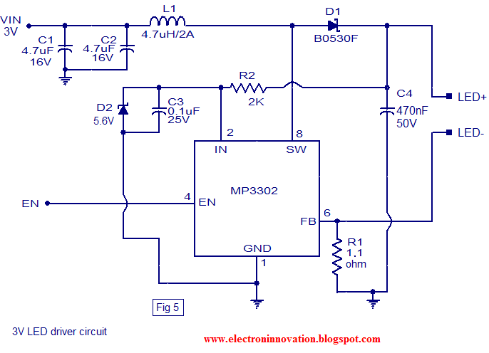
No comments:
Post a Comment